Inventor 超入門:[面取り]コマンドでエッジを面取りしてみました!①
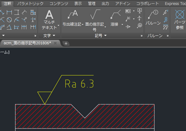
機械部品などに尖っている角部分があると危険なので大抵の場合、角は面取り処理が行われますよね。
3次元設計でも面取りしたい部分には面取りの3D形状を作成します。Autodesk Inventorの[面取り]コマンドは色々な面取り形状を作成できますが、ここでは基本的な使い方を確認してみました。
[面取り]コマンドを実行する!
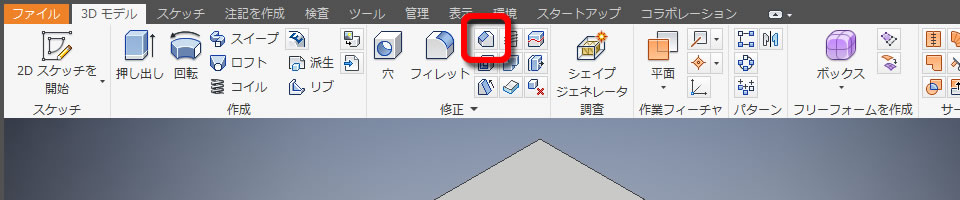
[面取り]コマンドは、リボンメニューの[3Dモデル]タブの[修正]パネルにあります。
エッジを選択する!
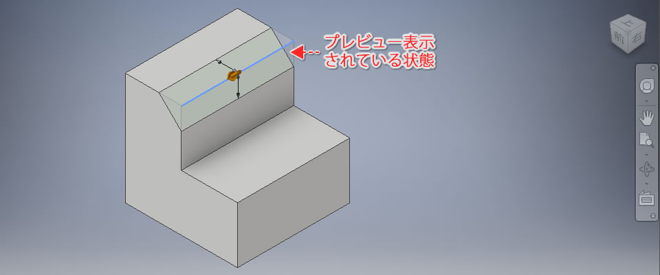
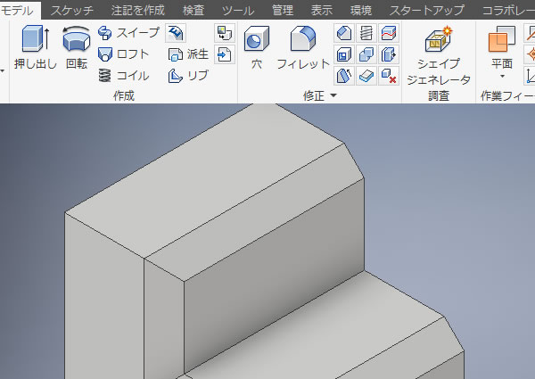
面取りを行うエッジを選択すると、面取りされた形状がプレビュー表示されました。
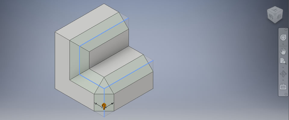
エッジは複数選択でき、選択する箇所によって面取りの形状は自動で処理されました。
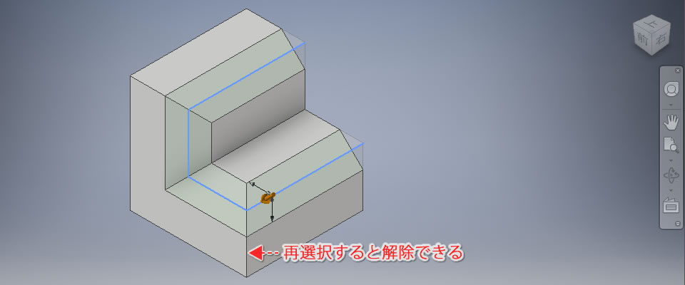
エッジを誤って選択してしまったときは、再選択することで簡単に解除できました。
面取りの種類を選択する!
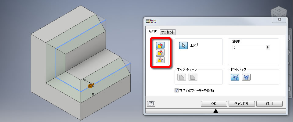
[面取り]ダイアログボックスの[面取り]タブにあるアイコンで面取りの種類を指定できます。
ここでは両面の角(エッジ)から同じ距離で面取りされる[距離]を指定しました。
距離を入力する!
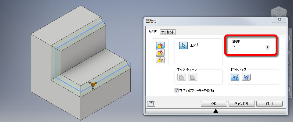
面取りの距離は[面取り]ダイアログボックスで入力できます。
数値を変更するとプレビューも変更されるので、作成する面取りの形状を確認しながら数値を決めることができます。
3D形状を確定させる!
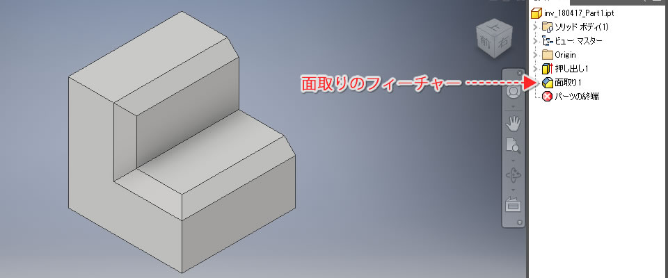
面取りを行うエッジと距離が決まったら、[面取り]ダイアログボックスにある[OK]ボタンをクリックします。
これで3Dモデルのエッジが面取りされました!
ブラウザを確認すると「面取り」のフィーチャーが追加されていました。
【動画で見てみましょう!】
参考記事
Warning: file_get_contents(): https:// wrapper is disabled in the server configuration by allow_url_fopen=0 in /home/ccube/cadcam.ne.jp/public_html/cad100blog/wp-content/themes/cad100blog-2024/functions.php on line 1040
Warning: file_get_contents(https://www.youtube.com/watch?v=bM2rI2ThrPI&t=5s): Failed to open stream: no suitable wrapper could be found in /home/ccube/cadcam.ne.jp/public_html/cad100blog/wp-content/themes/cad100blog-2024/functions.php on line 1040

Warning: file_get_contents(): https:// wrapper is disabled in the server configuration by allow_url_fopen=0 in /home/ccube/cadcam.ne.jp/public_html/cad100blog/wp-content/themes/cad100blog-2024/functions.php on line 1040
Warning: file_get_contents(https://knowledge.autodesk.com/ja/support/inventor-products/learn-explore/caas/CloudHelp/cloudhelp/2018/JPN/Inventor-Help/files/GUID-D40DA0A5-0547-41FE-A1BC-0B42AE1CC8E4-htm.html?v=2018&st=%E9%9D%A2%E5%8F%96%E3%82%8A): Failed to open stream: no suitable wrapper could be found in /home/ccube/cadcam.ne.jp/public_html/cad100blog/wp-content/themes/cad100blog-2024/functions.php on line 1040